Debugging the openEEG-Hardware
(updated 2003-11-24)
modularEEG V1.0,V0.7,V0.6
Before debugging and testing the following should be read and
understood:
http://openeeg.sourceforge.net/doc/modeeg/modeeg.html
digital part
The debugging and testing procedures described can be used with
the following hardware versions:
- V1.0(Programming port has same layout as V0.7)
- V0.7(Programming port J101 has new layout with 10 pins)
- V0.6(Programming port J101 has old layout with 6 pins)
All hardware versions can use as IC102 either the
- AT90S4433 (quite outdated, difficult to buy) or the
- ATmega8 (more features, however only 4 ADC channels with 10bit
and 2 channels with 8 bit resolution)
Requirements for debugging and testing
Note: The
modularEEG itself is platform independent, however some of the tools
and procedures I will describe here will only work on Windows OS. Linux
should also work, however other software will be required.
- PC with
- serial (com, RS232) port to connect the modularEEG
- parallel (LPT, printer) port to connect to the modularEEG
proramming port
- Serial cable (as
described in the schematics (inside ModularEEG package))
to connect the
modularEEG with the com-port of the PC.
- Programming cable
(Programming adapter, Programming dongle)
- V0.6 requires a parallel port programming adapter cable with 6
poles as
described in V0.6 "cables.sch" (eagle file)
- V0.7, V1.0 and higher requires a parallel port programming
adapter cable with 10 poles as
described in V0.7, V1.0 "cables.sch" (eagle file) or
- the OLIMEX parallel programming adapter
(AVR-PG2B
(PARALLEL PORT) 10 PIN ICSP AVR MICROCONTROLLER PROGRAMMER)
Note: The OLIMEX AVR-PG1B -
STKxxx COMPATIBLE ICSP SERIAL PORT DONGLE PROGRAMMER will work also but
requires another programming software (e.g. Pony Prog from
Claudio Lanconelli) - I have not tested this combination, so you are on
your own if you want to use it.
- Programming software
(e.g. SP12)
for flashing the firmware into
the modularEEG uP.
- download the appropriate SP12 package for your OS.
- The features of sp12 version 2.0 are explained in sp12.txt.Separate
readme's for each operating system describe the installation, and the
runtime config files also have their own docs;
look for those in the packages.
- firmware HEX-file for
AT90S4433 or for ATmega8
- Terminal program (e.g. Hyperterminal (delivered with every
Windows OS))
- ElectricGuru or some
other program that can receive data from the
modularEEG and display them as ADC-value over time.
- Multimeter for measuring
some DC voltages (and sometimes DC
currents)
- Mini speaker or
headphones (a crude method to check some AC
waveforms. Of course an oscilloscope would be much better if available)
- The printed schematics and pcb
layouts (In EAGLE CAD select
layers of interest and do a "ratsnest" to process copper polygones
before printing) so that you can easily identify parts and pins (e.g.
J101 PIN1)
- Some isolated wires
(inner diameter ca 0.5mm. Lace(cord, flex)
will not work well). For some diagnosis procedures you will be asked to
unplug some ICs and make some connections by plugging the wire ends
(ca. 5mm isolation removed) into the emtpy IC sockets. So most (but not
all) diagnosis connections can be done without soldering.
| Problem |
Reason
|
Procedure
|
- SP12 programming software does not recognize the uP Type
- firmware can not be flashed
|
- modularEEG has no power (e.g. low battery)
- wrong programming adpater
- wrong parallel port (the physical port of the PC and the
port address in the SP12 configuration file must match)
- Programming adapter shifted or rotated on J101. Make sure
that J101 pin 1 matches with the red (sometime marked blue) cable of
the programming adapter.
- wrong KANDA mode (SP12)
# Set KANDA=1 to adapt the parallel port pinout
# to the cable/dongles supplied with the
# Atmel/Kanda STK200/300 starter kits.
# When KANDA=0 (default) the pinout conforms
# to the original SP12 cable and Ken Huntington's
# dongle.
KANDA=1 is also required with the OLIMEX parallel programming adapter
(AVR-PG2B (PARALLEL PORT) 10 PIN ICSP AVR MICROCONTROLLER PROGRAMMER)
- direct parallelport access not enabled (Win NT,2000,XP)
(does not apply to Win95,98,98SE,ME)
- wrong timing (with SP12) on LPT2 with Multi IO-card.
After creating "_sp12rc" with (sp12.exe -i) following entries
have to be changed for LPT2 on 222N-2 Multi IO-card
(NetMosMultiFunction, PCI, 9835 Multi-I/O Chip, Win98SE, 1.333Ghz
ATHLON) :
file: _sp12rc
...
# This port address will be used:
PORT=0x278
(This is LPT2)
...
# Set clockSpdDefault to a suitable value in MHz.
CLOCKSPDDEFAULT=0.1
...
(The default value of 0.7 results in abort after 3 write retries)
|
|
device
does not send any data to
the PC (running hyperterminal)
|
|
|
- PC com port does not work
- Serial (RS232) cable
- defective (e.g. swapped pins, broken wires, shortcuts)
- connected to other port that set up in hyperterminal
|
PC
loopback test |
- IC106 (MAX232) defective
- C127,128,126,129 mounted with false polarity or have less
voltage than specified.
- Optocouplers defective (IC104) or inserted with wrong
orientation (be carefull: IC104 is rotated 180 deg due to layout
reasons) (IC103 is only for receiving data),
wrong resistor values around IC104, broken traces, shortcuts.
|
uP
loopback test
TxD Speaker test
|
- IC102 (AT90S4433, ATmega8) not flashed with firmware.
- XTAL X101 not oscillating
|
|
data sent from EEG to PC does
not make sense
|
AT90S4433 and ATmega8 require
_different_ firmware versions.
ATmega8 requires proper flashing of the fuses, otherwise it will run on
internal 1Mhz. |
Check fuses of ATmega8
TxD
Speaker test
|
How to flash the firmware
(AT90S4433 version) on Win NT/2000/XP
Requires:
- programming cable: 10 pole SP12 compatible from "cable.sch"
schematic (V0.7 and later)
- PC parallelport LPT1 on the mainboard
- modularEEG hardware version: V0.7 and later
- Operating system (OS): Windows XP
Download the "sp12 v2.0.7 for XP/NT/W2000" package from
http://www.xs4all.nl/~sbolt/e-spider_prog.html#NT_version
or directly from:
http://www.xs4all.nl/~sbolt/Packages/sp12v2_0_7-Win32.tgz
Unpack the tgz archive file until you get the SP12v2_0.7 folder.
Follow these instructions:
(If you have already installed GIVEIO or some other driver that enables
direct port access under Windows XP you can skip the first part)
From "readme.win" in
"sp12v2_0_7-Win32.tgz.gz"
...
INSTALLATION
If you are running Win NT/2000/XP, you
will need to install the GIVEIO device driver.
Installing Giveio:
To install the device driver you need Dale Roberts' device
driver
giveio.sys and the program instdrv.exe. Both of
these are included
in the WinNT sub-directory of this installation. The
original files
and documentation for Giveio can be found at
(
http://www.ddj.com/ftp/1996/1996.05/directio.zip).
Instdrv is
from the device driver kit (DDK) for Windows NT.
* Copy the driver giveio.sys from the archive directio.zip
into
%SystemRoot%\system32\drivers.
* Use command line to install the driver using instdrv:
instdrv
giveio %SystemRoot%\system32\drivers\giveio.sys
* In order to start this driver at every reboot
automatically,
change the start up behaviour to automatic:
* 2000/XP: start regedit and
change the value of the key "Start" in
"HKEY_LOCAL_MACHINE\SYSTEM\CurrentControlSet\Services\giveio" to 2.
* NT: Control
Panel->Devices->giveio->Start Up->Automatic.
Sp12.exe should be put somewhere in your PATH. It is
advisable
to set the environment variable SP12 by adding a line like
"Set SP12=C:\SP12\" to your environment. Sp12 looks for
two
files in the directory pointed to by this variable:
_sp12dev and
_sp12rc. Without it, you'll need copies of those files in
all
your project directories.
Copy _sp12dev into the chosen directory, and run
sp12 -i
To make sp12 create an _sp12rc for your system. Depending
on your
computer it may take a few seconds or somewhat longer to
calibrate the timing loop.
Note: If heavy multitasking is going on, the
autocalibration will
produce time constants which are too small. Therefore
_sp12rc
should be created on a lightly loaded system. When
you are
actually programming an uC, heavy background loads may
slow down
the job, but they won't really hurt; the AVR serial mode
programming time constraints are minimum values.
_sp12rc is in plain language and may be edited (with
care), for
instance to make SP12 use a different parallel port (read
_sp12rc and sp12rc.txt for details).
Finally, run
sp12 -t
The command presents a progress bar, which should take
about 10
seconds to complete, counting from the moment when you hit
the
return on the command line. (There may a brief pause
before the
bar appears, which nevertheless is part of the ten
seconds.)
I wouldn't worry if it's eight or 15 seconds. But the
deviation
is large, read `bugs & bother' below.
...
Connect the programming cable (2x5, 10 poles, digital pcb version 0.7
and later) with the PC-parallelport and the modularEEG 2x5 pinhead
programming connector. Make sure PIN1 of the connector is aligned with
PIN1 of the programming cable.
Activate the power supply for the modularEEG.
Flash the ROM-image (
AT90S4433_modeeg_v0_07.rom)
into the AT90S4433 uP:
sp12.exe -wpfC AT90S4433_modeeg_v0_07.rom -T1
You should see the following:
SP12 version 2.0.7 performing init...
Path to _sp12rc and _sp12dev: Local directory
Running in SP12 cable/dongle compatible mode.
Enabling AVR serial reading/programming...
The device code bytes 0,1,2: 0x1e, 0x92, 0x3 were read
from parallel port 0x278 and indicate the following:
You have connected an AT90S4433
The device was made by Atmel
Performing chip erase...
Writing content of AT90S4433_modeeg_v0_07.rom into program area.
...............................................................
ooooooooooooooooooooooooooooooooooooooooooooooooooooooooooooooo
...............................................................
ooooooooooooooooooooooooooooooooooooooooooooooooooooooooooooooo
AT90S4433_modeeg_v0_07.rom written and verified.
write retries: 0, byteWrite: 25 percent of default
...............................................................
ooooooooooooooooooooooooooooooooooooooooooooooooooooooooooooooo
Checksum program area: 4893
Reset was left high.
If you see the above you have successfully flashed the firmware into
the uC.
One final but important step:
DANGER!
|
Always disconnect the SP12cable before connecting
the EEG to a test subject !!!!
That is important
because the programming cable (SP12cable) crosses the opto-isolator and
connects PC-ground to EEG-Ground. So with the programming cable
attached the modularEEG does not have any safety isolation. |
How to set up and use hyperterminal
A pictured example how to make a direct COM - connection to a modem can
be found here:
(
http://www.eicon.com/support/helpweb/diva/hyperterminal.asp)
and here:
http://www.umanitoba.ca/acn/remote/faq/hyper-using.html
Here is a simliar procedure for the modularEEG:
Launch the HyperTerminal program:
- Click Start > Run
- In the box which appears type in: HYPERTRM
(note that the "e" in
"term" is missing)
- Click OK.
If you see the error message 'Cannot find HYPERTRM' you will need to
Install HyperTerminal:
- Click Start > Settings > Control Panel > Add / Remove
Programs.
- In Add / Remove Programs select Properties and then click the
Windows Setup tab.
- Double-click Communications
- Check the box for HyperTerminal
- Click OK, and then OK again to install.
Note: You may be asked for your Windows
installation disk for this procedure.
(If HyperTerminal is already installed you can alternatively start it
by following the Start menu to Programs - Accessories - HyperTerminal
(The exact position varies slightly for different Windows versions))
BTW: You can use any other terminal program. There is nothing special
about
hyperterminal besides that it is distributed with Windows95, 98, Me,
NT, 2K & XP
Setting com port, protocol and baud rate
A pictured example can be found here:
http://www.stepperboard.com/using_windows_hyperterminal.htm
Setting protocol and baud rate for the openEEG:
- When Hyperterminal first loads via the "Hyperterminal" link, it
will ask for a new connection. I suggest that you enter something
descriptive, like "openEEG".
- It will next ask for a "Connect to" request. Select the COM
port which is connected to the openEEG unit.
- It will then ask for the port settings. Select:
- 57600 baud,
- 8 data bits,
- no parity ("none"),
- 1 stop bit,
- flow control off ("none").
At this point you will see data from the openEEG scroll down the
screen, if it is connected and powered.
Some final steps:
- You will also want to access the "File->Properties" page,
"Settings" tab.
- Adjust the "Emulation" to be TTY,
- Press the "ASCII Setup" button, and uncheck
"echo typed characters locally"
(this is that the local echo is not
misinterpreted when doing the hardware loopback test)
PC loopback test
No power (for the device) is required for this test.
- Unplug IC106 (MAX232).
- Connect IC106 (empty socket) PIN 14 with PIN 13 with a piece of
wire.
You now have a simple loopback circuit that echoes any data on (PC
side) TxD to RxD.
Now use a terminal program (Hyperterminal),
- disable the local echo mode,
- set the com-port the openEEG is connected with
- (baudrate etc. is irrelevant this time),
- select "no protocol" (or no handshaking).
You should now get an echo of any character you type in.
Disconnect IC106 (empty socket) PIN 14 and PIN 13 (remove the wire
inserted above).
You should no more get an echo of any character you type in.
If all of this works you have just verified the correct operation of:
uP loopback test
(has to be written)
Checking fuses of ATmega8
Make sure the device has power.
Connect the programmer cable.
Type to read out the fuses of your ATmega8:
sp12.exe -rF
If you get the text below ( CKSE is 0001 ), your ATmega8 runs on
internal 1Mhz instead of using the external 7.3728Mhz XTAL.
"...
SP12 version 2.0.7 performing init...
Path to _sp12rc and _sp12dev: Local directory
Running in SP12 cable/dongle compatible mode.
Enabling AVR serial reading/programming...
The device code bytes 0,1,2: 0x1e, 0x93, 0x7 were read
from parallel port 0x378 and indicate the following:
You have connected an ATmega8
The device was made by Atmel
11100001 are the fuse bits read from an ATmega8
0xxxxxxx - BODLEVEL 4V (default 2.7V)
x0xxxxxx - brownout detection enabled
xxSUxxxx - reset delay, datasheet p28
xxxxCKSE - clock select, datasheet p24
..."
To fix the problem try this here:
sp12.exe -wF11111111
TxD Speaker test
Power on.
All ICs inserted:
Connect a little speaker or earphone from IC106 PIN14 (TXD) to GND1.
Does it sound like this here?
http://www.jhansmann.de/eeg/hardware/modeeg_speaker_txd.mp3
- If the sound has lower pitch there is a problem with the XTAL
frequency or ATmega8 fuses.
- If you do not hear any sound the data path from IC102 PIN3 to
IC106 PIN14 is somewhere interrupted.
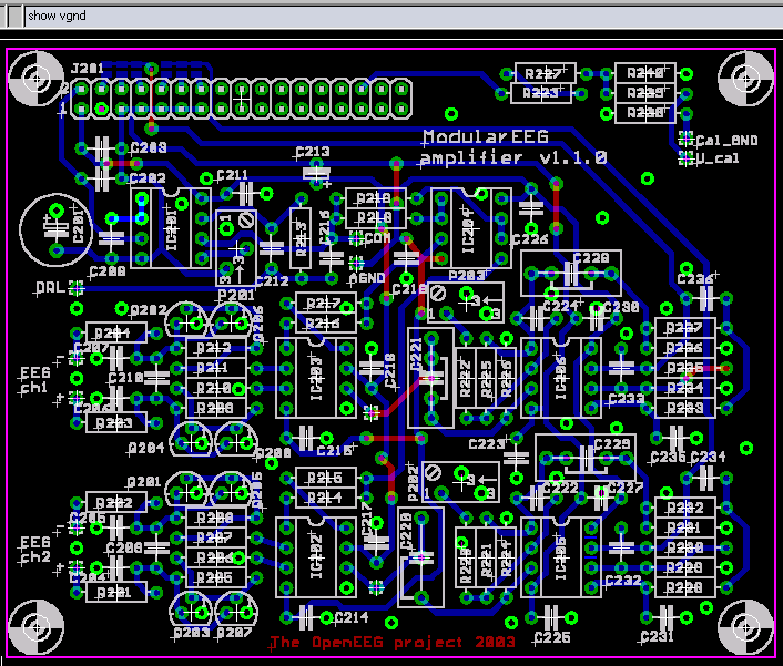
Finding VGND
Here is a picture of the modularEEG analog pcb with all VGND pins and
vias highlighted in green:
VGND highlighted in EAGLE