The modEEGsmd
A modular single channel bluetooth EEG based on the modularEEG
(updated 20070312)
Authors of modEEGsmd:
| Nicholas Ord: | Idea, mechanical design (stacking etc.), first schematics and layouts, smd parts selection, pcb and prototype production. testing and calibration - Special thanks to Nicholas for generously completely funding my prototype inclusive bluetooth adapters! |
| Joerg Hansmann: | Schematic review and tweaking, final EAGLE pcb layout, testing |
modEEGsmd_1channel_v1.15 schematic
(150dpi.png)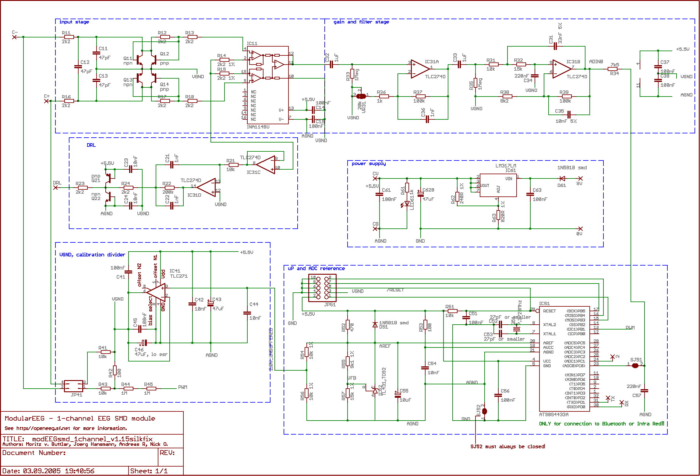
pcb layout modEEGsmd_1channel_v1.15
(with silkfix according to OLIMEX production standards)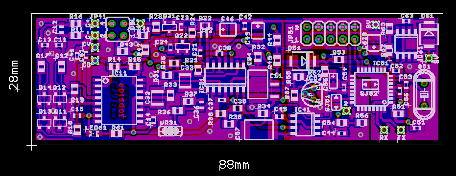
Download EAGLE CAD files:
modEEGsmd_1channel_v1.15silkfix_EAGLE_CAD_files.zip (90KB)modEEGsmd with Bluetooth module (linTech 1408_CL2)
The 2 x1.2k divider is for reducing the 5.5V Tx level from the ATmega8 down to 2.75V compatible with the linTech 1408_CL2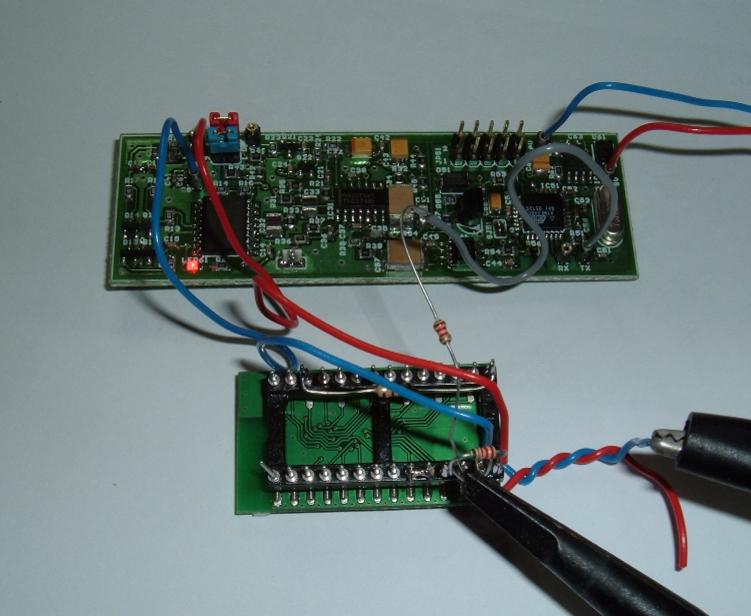
PC side Bluetooth Adapter (linTech 1409S)
Rx Tx crossed over cable from PC to linTech 1409S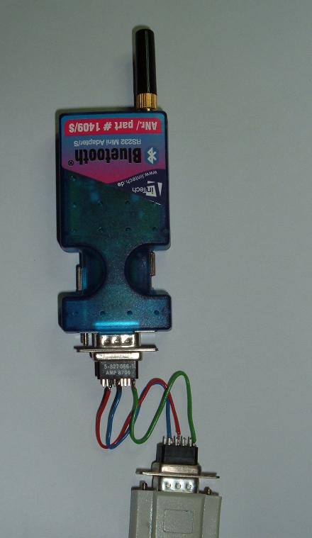
IMPORTANT WARNING
If you choose to use the OpenEEG project hardware and/or software to do biofeedback training or experimentation on yourself or others, you do so ENTIRELY AT YOUR OWN RISK.
The software and hardware designs are distributed in the hope that they will be useful, but WITHOUT ANY WARRANTY; without even the implied warranty of MERCHANTABILITY or FITNESS FOR A PARTICULAR PURPOSE.
Whilst our aim is to create a genuinely useful set of tools for neurofeedback training and experimentation, it is quite possible that our software, hardware or its accompanying documentation contain bugs or mistakes which its authors cannot be held responsible for. Please bear in mind that we are a group of experimenters and enthusiasts, and many of us have no formal training or qualifications in this field.
Doing neurofeedback training can also cause unpleasant side-effects for a small number of people, or in certain unusual circumstances. In an attempt to provide information to allow you to better judge the risks to yourself, we are listing here the ones we are aware of. (Remember, though, we are not experts, and you should research the subject yourself if you want to be sure):
- Electrocution. If there is an isolation failure in the EEG unit (for example through faulty construction), and the EEG subject touches a live mains voltage (for example, touching an appliance where the earthing has failed and there is a short-circuit to the casing), then the mains voltage will take the shortest route to earth. This means passing up the arm, to the head, through the electrodes, through the isolation failure in the EEG unit, to the PC and then to earth. This electric shock to the head is likely to have severe consequences. It is important to take care when building the EEG unit to make sure that the isolation is not compromised.
- Anxiety attacks.
- Stimulation of latent seizure activity to full seizure activity.
Disclaimer for the EEG designs on this page and all related files:
The EEG designs on this page are _not_ FDA nor IEC601-1 approved. Therefore they must _not_ be connected via electrodes with humans or animals. Doing so is potentially hazardous and might result in electric shock.
The EEG designs on this page are only intended to be an engineering example for making electrical measurements under simulated electrical conditions and a platform for developing firmware for the microcontroller in the modularEEG or RS232EEG circuit and the host PC.
The EEG designs are presented as an engineering example of some design techniques used in digitizing brainwave signals. They are not medically approved devices, no medical claims are made for these devices, and they should not be used for medical diagnostic purposes.
The authors do not guarantee that the data provided in the above mentioned files is complete or appropriate for any particular application.
The authors are not responsible for any damages you may suffer
as a result of using/building/programming the EEG devices. This
includes also damages to
your computer or any device connected to the EEG devices.