Input side multiplexed EEG
A modular multi channel (e.g. 20+) low cost EEG based on the modularEEG
Contributors:
| OLIMEX Ltd Support: Tsvetan Ivan |
Proposing direct analog multiplexing of the electrode signals and providing some quite solid facts that it can be done. |
| openEEG list | All the people in the last years who were keen enough to propose direct analog multiplexing of the electrode signals. |
| Joerg Hansmann: | LTspice simulations |
The ideas presented here are based on theory and simulations
only. So far no working prototype has been built (by me or OLIMEX).
Instrumentation amplifiers and filter stages with low tolerated parts
are quite expensive. Conventional EEG amplifiers like the ModularEEG
need n (n = number of channels) instrumentation amplifiers and bandpass
filter/gain stages. The output of the analog processing chain then goes
into an analog multiplexer and further into the ADC (mux and ADC are
inside the ATmega8 uC).Another approach (the one discussed here) is the idea of using 1 of the expensive amplifiers and multiplex n electrodes at the input side of the amplifier. However this is not so easy and straight forward as the above conventional approach. In fact it is really challanging from the EE point of view.
Definition of design goals (updated 20070527)
With all the input and good ideas and comments from the openEEG list it is very easy (at least for me) to go astray and forget what the primary intention for this development was.| Primary features: |
|---|
|
|
|
|
|
|
|
|
The simulations in reverse order (most recent ones on top of the page)
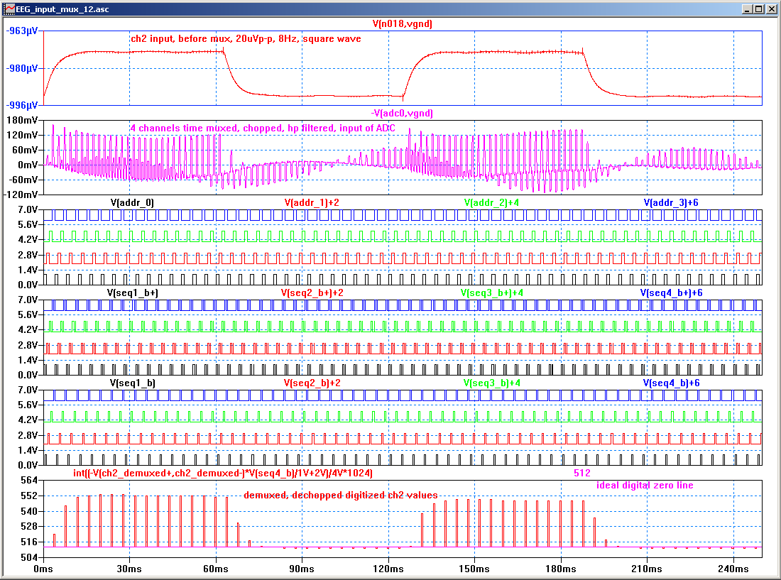
(updated 20070527)V0.12 (updated 20070517)
pdf schematic: EEG_input_mux_12.asc.pdfsimulated waveforms: EEG_input_mux_12.plt.png
V0.09 (updated 20070513)
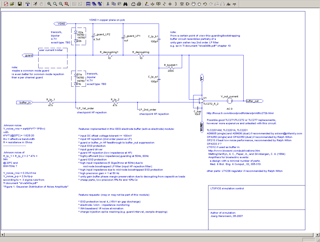
pdf Schematic: EEG_input_mux_09.asc.pdf
Subcircuit schematic: buffer_09.asc.png:
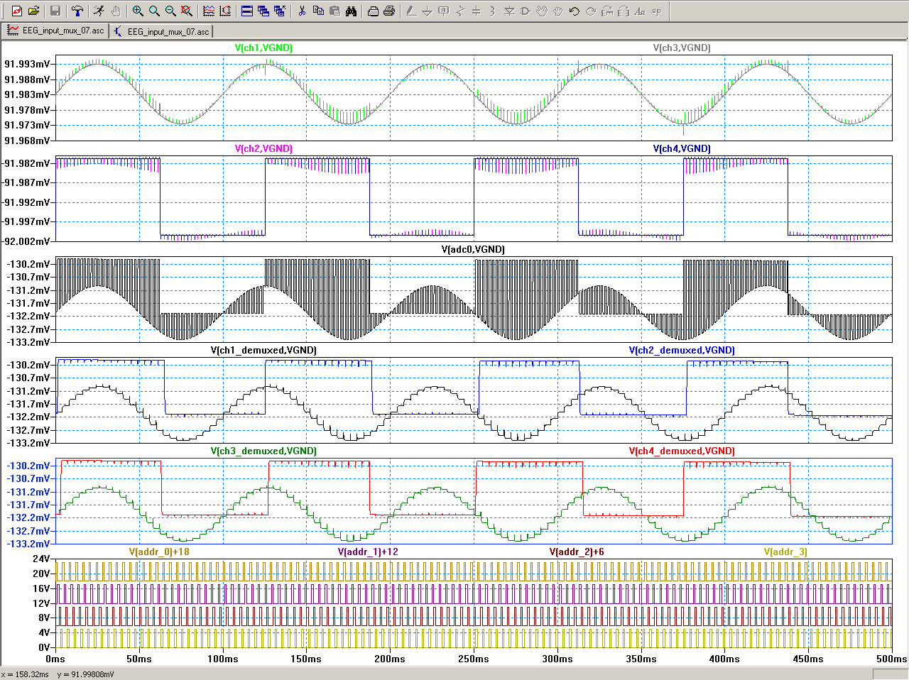
V0.07 (updated 20070509)
Proof of concept with a 4 channel input side multiplexing EEG amplifier connected to a quite challanging benchmark generator:missing:
1)ESD protection
2)DRL circuit (signal derived from the (-) side of the inst amp gain setting R)
3)2nd gain stage (G=80)
LTspice simulation file - EEG_input_mux_07.asc
LTspice plot file - EEG_input_mux_07.plt
pdf Schematic of EEG_input_mux_07.asc
LTspice simulated waveforms :
Some unsorted excerpts/thoughts from my email correspondence with OLIMEX so far:
----------
EEG electrode offset voltages can be as high as +-100mV.Now think of a condition where each even electrode has +100mV and each odd one -100mV.
If you multiplex through these electrodes you get 200mVp-p AC at the EEG amplifier input. At a nominal gain of G=7812 (as in ModularEEG) this will drive the amplifier into clipping.
------------
Also,
when you say that low-pass filtering can be done after demuxing, the only
way I see it is by implementing a digital filter in software.
Software is the preferred solution.
This however could also be implemented in hardware (see schematic at the far right side).
What I am thinking is a passive low-pass filter with a fc of about 50Hz
before the mux for each channel,
Such low fc will require high Rs and Cs. This is not desirable, because the Cs would be in parallel with each input and present a very bad (low) impedance for the electrodes. (When I have put C_lp_1..5 (only 15pF) into the simulation the common mode rejection for asymmetric electrode impedances dropped significantly. Even higher Cs would be desastrous)
followed by differential input stage. After
that an active high-pass filter with a fc in the range of 0.1-0.5 Hz and a
gain stage with flat frequency response.
A passive HP filter between inst amp output and 2nd gain stage input would be enough.
It's output goes to the ADC where
it is sampled.
The DRL integrator should be fed from the output of the differential input
stage and this way should compensate all currently measured channels
(similar to what is already present in the two-channel version).We would be
experimenting with this idea in the near future.
I strongly recommend the (referential) setup in the simulation schematic, because it reduces the number of input wires compared to pairs of +- inputs (as in the modularEEG)
See the simulated waveforms in "EEG_input_mux_07.plt.png" as a proof of concept.
Some parts are however missing:
1)ESD protection
2)DRL circuit (signal derived from the (-) side of the inst amp gain setting R)
3)2nd gain stage (G=80)
The attached *.asc and *.plt file are LTSPICE files (LTSPICE/switchercad is a freeware SPICE simulator from linear.com).
If you want to play through some ideas you can easily do this in the simulation.
------------------
I have to check this here out too:
-------- Original-Nachricht --------
Betreff: Re: [Openeeg-list] Interest in multi-channel eeg
Datum: Fri, 4 May 2007 20:59:01 +0000 (UTC)
Von: Nathan Whilk <nathanwhilk@yahoo.com>
Antwort an: Discussion of EEG hardware, software, training protocols, NFB theory - for developers and users. <openeeg-list@lists.sourceforge.net>
An: openeeg-list@lists.sourceforge.net
...
There was some interesting discussion of a multiplexing approach
beginning with a 28 Jan, 2007, post under the not-so-illuminating
subject line "hi". ( It was really well-written, I thought, and
had the added attraction that I was actually able to follow most
of it! )
...
-------------------
Further possible problems:
- charge injection of the analog multiplexer
- DRL implementation with multiplexed signals
- increased wideband noise level
IMPORTANT WARNING
If you choose to use the OpenEEG project hardware and/or software to do biofeedback training or experimentation on yourself or others, you do so ENTIRELY AT YOUR OWN RISK.
The software and hardware designs are distributed in the hope that they will be useful, but WITHOUT ANY WARRANTY; without even the implied warranty of MERCHANTABILITY or FITNESS FOR A PARTICULAR PURPOSE.
Whilst our aim is to create a genuinely useful set of tools for neurofeedback training and experimentation, it is quite possible that our software, hardware or its accompanying documentation contain bugs or mistakes which its authors cannot be held responsible for. Please bear in mind that we are a group of experimenters and enthusiasts, and many of us have no formal training or qualifications in this field.
Doing neurofeedback training can also cause unpleasant side-effects for a small number of people, or in certain unusual circumstances. In an attempt to provide information to allow you to better judge the risks to yourself, we are listing here the ones we are aware of. (Remember, though, we are not experts, and you should research the subject yourself if you want to be sure):
- Electrocution. If there is an isolation failure in the EEG unit (for example through faulty construction), and the EEG subject touches a live mains voltage (for example, touching an appliance where the earthing has failed and there is a short-circuit to the casing), then the mains voltage will take the shortest route to earth. This means passing up the arm, to the head, through the electrodes, through the isolation failure in the EEG unit, to the PC and then to earth. This electric shock to the head is likely to have severe consequences. It is important to take care when building the EEG unit to make sure that the isolation is not compromised.
- Anxiety attacks.
- Stimulation of latent seizure activity to full seizure activity.
Disclaimer for the EEG designs on this page and all related files:
The EEG designs on this page are _not_ FDA nor IEC601-1 approved. Therefore they must _not_ be connected via electrodes with humans or animals. Doing so is potentially hazardous and might result in electric shock.
The EEG designs on this page are only intended to be an engineering example for making electrical measurements under simulated electrical conditions and a platform for developing firmware for the microcontroller in the modularEEG or RS232EEG circuit and the host PC.
The EEG designs are presented as an engineering example of some design techniques used in digitizing brainwave signals. They are not medically approved devices, no medical claims are made for these devices, and they should not be used for medical diagnostic purposes.
The authors do not guarantee that the data provided in the above mentioned files is complete or appropriate for any particular application.
The authors are not responsible for any damages you may suffer
as a result of using/building/programming the EEG devices. This
includes also damages to
your computer or any device connected to the EEG devices.